Category

Home » Application » Isolate Frequency Converter Fault
Isolate Frequency Converter Fault
Induction motor powered by frequency converter may require additional testing following a fault identified as a stator related anomaly. If the inner phase insulation is damaged or weak, the rapid voltage rise seen from many frequency converters can result in inner phase currents sufficient to cause the frequency converter failure. This article is designed to give the analyst additional motor circuit evaluation test data, using the motor circuit evaluation for de-energized testing, to better isolate the cause of the failure to the frequency converter or motor. It is applicable only for induction motors with >3 leads exposed at the connection box.
Procedures/Instructions
Six Lead
Nine Lead
By charging the inner phase insulation system with a DC potential, weaknesses between phases can be identified as the root cause of the frequency converter failure. Identifying the induction motor rather than the frequency converter as the root cause can prevent costly frequency converter replacements.
Procedures/Instructions
Six Lead
-
Disconnect the frequency converter from the induction motor when performing motor circuit evaluation (de-energized) testing.

- Disconnect all induction motor leads from each other to isolate the phases.
- Connect induction motor leads 2 and 3 together
- Connect Black (phase 1) lead to induction motor lead 1. Connect green (ground) lead to the connected induction motor leads 2 and 3.
- Perform a dielectric absorption test to determine the integrity of the inner phase insulation system.
- Disconnect all induction motor leads from each other to isolate the phases.
- Connect induction motor leads 1 and 3 together.
- Connect Black (phase 1) lead to motor lead 2. Connect green (ground) lead to the connected induction motor leads 1 and 3.
- Perform a dielectric absorption test to determine the integrity of the inner phase insulation system.
- Disconnect all induction motor leads from each other to isolate the phases.
- Connect motor leads 1 and 2 together.
- Connect Black (phase 1) lead to motor lead 3. Connect green (ground) lead to the connected induction motor leads 1 and 2.
- Perform a dielectric absorption test to determine the integrity of the inner phase insulation system.
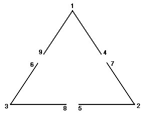
Nine Lead
-
Disconnect the frequency converter from the induction motor when performing motor circuit evaluation (de-energized) testing.

- Disconnect all motor leads from each other to isolate the phases.
- Connect induction motor leads 2 and 3 together.
- Connect Black (phase 1) lead to motor lead 1. Connect green (ground) lead to the connected motor leads 2 and 3.
- Perform a dielectric absorption test to determine the integrity of the inner phase insulation system.
- Disconnect all induction motor leads from each other to isolate the phases.
- Connect induction motor leads 1 and 3 together.
- Connect Black (phase 1) lead to motor lead 2. Connect green (ground) lead to the connected motor leads 1 and 3.
- Perform a dielectric absorption test to determine the integrity of the inner phase insulation system.
- Disconnect all induction motor leads from each other to isolate the phases.
- Connect induction motor leads 1 and 2 together.
- Connect Black (phase 1) lead to motor lead 3. Connect green (ground) lead to the connected induction motor leads 1 and 2.
- Perform a dielectric absorption test to determine the integrity of the inner phase insulation system.
By charging the inner phase insulation system with a DC potential, weaknesses between phases can be identified as the root cause of the frequency converter failure. Identifying the induction motor rather than the frequency converter as the root cause can prevent costly frequency converter replacements.
Post a Comment:
You may also like:

