Category

Home » Wiki
Simple answer is: mass and volume. Higher frequency means reduced material (and thus volume / mass) for transformers and rotating machines.
Practical limit is around 400 Hz - much higher, and the magnetic components get pretty esoteric to minimize losses. They'd also start to have issues with prime movers and/or interference with VHF/UHF bands for communication purposes.
In a small system like aircraft reducing the weight of the system is given priority, so higher frequency like 400 Hz (limited by losses). Power density of the machine can be increased either by increasing torque/speed, but increasing torque requires higher volume....so turbine driven alternators of aerospace applications always run at few kilo rpm.
As per my knowledge, reduction in inrush current by transformer design changes (low flux density or increased impedance) is marginal. Leakage % impedance will not reduce inrush, but only air core inductance of the energized winding. Inrush current = (peak of phase voltage/ impedance consisting of air core inductance + winding resistance) x factor based on flux density. This is my experience as a transformer designer for nearly half a century. In transformer classics (see page 37 of Transformer Engineering -LF Blume of GE, 1951) where measures for reducing inrush current are discussed, never the above type of design changes are proposed as a solution. Pre charging etc were mentioned in such texts, but today controlled switching is the accepted solution to reduce inrush currents.
Some facts on modern power transformers compared to those of 30-40 years back. This may be contrary to the recordings in old transformer text books.
Some facts on modern power transformers compared to those of 30-40 years back. This may be contrary to the recordings in old transformer text books.
All large power supply systems (sized to power cities) need to have frequency and voltage relays to drop load when the system begins its oscillation (when generation and load are out of balance). This is done to attempt to match load and generation. I live in the Western US have seen large scale load drops (large portions of cities, affecting millions of customers) due to large transmission line outages that caused a mismatch in generation vs load, causing voltage and frequency oscillation, which in turn tripped off loads (over and under frequency and voltage relays). This large scale drop in loads (at different frequencies and voltages, done in stages) finally matched generation to loads and stabilized the system. Depending on the size of your system, stages of frequency and voltage relays connected to most of the distribution circuits can help prevent a total collapse of your power supply system.


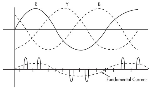
The input circuitry of most static frequency converters is essentially a three-phase diode rectifier bridge with capacitor filter. The input current to such a circuit consists, on each input phase, of pulses of current that charge the storage capacitor as show in following figure. Input current is therefore a distorted current waveform, with a fundamental component at supply frequency, but with considerable harmonic content.

Input current drawn is essentially independent of the converter output frequency since the instantaneous power drawn by the static frequency converter is a constant, and therefore the current required from the input to charge the capacitor on the DC bus is a constant.

Input current drawn is essentially independent of the converter output frequency since the instantaneous power drawn by the static frequency converter is a constant, and therefore the current required from the input to charge the capacitor on the DC bus is a constant.
Please pay attention to internal high voltage components of the frequency converter, only qualified electricians can maintain and troubleshoot the frequency converter. Turn off the frequency converter before proceeding troubleshooting procedures if it's not necessary to do a live troubleshooting.
GoHz frequency converters do not require daily maintenance, but a regular maintenance is benefited of longer lifetime, the maintain times is in accordance with the environmental conditions.
Preventive Measures:
GoHz frequency converters do not require daily maintenance, but a regular maintenance is benefited of longer lifetime, the maintain times is in accordance with the environmental conditions.
Preventive Measures:
- Do not put any liquid objects on the top of the frequency converter.
- If the frequency converter is installed in a harsh environment, such as windy and dusty, pay more attention to make the frequency converter clean or do more frequent maintenances.
To realize high efficiency, great manageability and energy saving in industrial induction motor related applications, it is necessary to adopt controllable frequency converter systems. Frequency converter system nowadays is AC motor fed by a static frequency converter. The up-to-date frequency converter works great for AC motor applications and easy installation. One important issue, however, is caused by the non-sinusoidal output voltage. This factor has caused a lot of undesirable problems. Increased induction motor losses, noise and vibrations, detrimental impact on the induction insulation system, and bearing failure are examples of frequency converter related systems' issues. Increased induction losses mean a de-rating of the induction output power to prevent overheating. Measurement in the lab shows that temperature rises may be 40% higher with frequency converter compared with general power supplies. Continuous research and enhancement of frequency converters have solved many of these issues. Unfortunately, it seems that solving one problem has accented another. Reducing the induction and frequency converter losses tends to increase the detrimental impact on the insulation. The induction manufacturers are, of course, aware of this. New induction designs (inverter-resistant motors) are beginning to appear on the market. Better stator winding insulation and other structural improvements ensure induction motors that will be better adapted for frequency converter applications.
Induction motor systems consume approximately 65 percent of the $33 billion spent each year on electricity by domestic manufacturers. More than half of these induction motors are used in either fan or pump applications. This is why so many manufacturers are looking at frequency converters to reduce the power consumed in fan and pump applications. In fact, the physical size and, more importantly, the cost of converters have been reduced to levels where the payback in many instances is quite often one year or less!

Energy savings, which can be substantial, is not the only benefit of the installation of frequency converters, there are also additional savings realized in the reduction on wear and tear on the equipment. This savings, also significant, is not taken into consideration in the payback period described above.

Energy savings, which can be substantial, is not the only benefit of the installation of frequency converters, there are also additional savings realized in the reduction on wear and tear on the equipment. This savings, also significant, is not taken into consideration in the payback period described above.
Basically they are motor loads, for 3 phase induction motors voltage variation at motor nameplate frequency must be within plus or minus 10% and frequency variations at motor nameplate voltage must be within plus or minus 5%. The combined variation of voltage and frequency must be limited to the arithmetic sum of 10%. What is important is the flux density ratio, which is the ratio of line voltage over line frequency. If a 415V 50Hz motor with an FDR of 8.3vhz was to operate on 460V 60Hz with a FDR of 7.66vhz this would be okay as the percent variation is 8.35& which is below the 10% allowable arithmetic variation.
With fans, look at the fan curve. Changing from 50Hz to 60Hz increases the rotation speed of the fan to require more power than the motor is capable of. This may well push the fan to overload. Fans are usually sized very close to the available power of the motor and have little margin. Many have to change to a fan with less pitch to operate at the higher speed. Simple enough to do ahead of time but not so if you learn about after burning out the motor.
With fans, look at the fan curve. Changing from 50Hz to 60Hz increases the rotation speed of the fan to require more power than the motor is capable of. This may well push the fan to overload. Fans are usually sized very close to the available power of the motor and have little margin. Many have to change to a fan with less pitch to operate at the higher speed. Simple enough to do ahead of time but not so if you learn about after burning out the motor.
For small hobby type applications or basic agricultural requirements where you just want to get a small three phase supply to power a lathe, drill, drive belt etc there is a basic device called a static frequency converter. If you look this up in Google you will get lots of hits. Try looking on Google images and you will see what is going on inside. You will need to know the power or horsepower rating of the motor in order to determine the correct capacitors. This is low cost & basic. It may cause the motor to get a bit hot due to poor phase balancing and so may restrict the power you can get out of the motor. Lots of low cost devices are on the market.
For larger applications you will probably need to go down the line of rotary converters (where a single phase motor drives a three phase generator) or a more sophisticated inverter design using thyristors and complicated electronics. Obviously these will have increasing complexity and associated cost.
For larger applications you will probably need to go down the line of rotary converters (where a single phase motor drives a three phase generator) or a more sophisticated inverter design using thyristors and complicated electronics. Obviously these will have increasing complexity and associated cost.
Frequency converter can be a great way to save money for your motor-related business. If your plants have a lot of induction motors or uses older style motors, then a frequency converter could make your plants more efficient and save money for you.
Using frequency converters in speed control of flow devices, such as pumps, fans and compressors, is not a new innovation. However, new technologies in these devices have lowered their cost making them much more attractive to across wide variety of uses. There is great potential to save energy by using more variable frequency control for induction motors.
Using frequency converters in speed control of flow devices, such as pumps, fans and compressors, is not a new innovation. However, new technologies in these devices have lowered their cost making them much more attractive to across wide variety of uses. There is great potential to save energy by using more variable frequency control for induction motors.
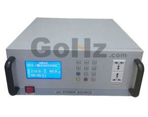
Static frequency converter means that's no rotary parts inside it - also called solid state - the definition is relative to rotary frequency converter which is using an electric motor to output adjustable frequency.

Static frequency converter is changing fixed grid power through AC to DC to AC by inner electronic parts and components, the multifunctional inverter converts the mains (50 Hertz or 60 Hertz, 120V, 240V, 400V) through conversion circuit and transforms into the required voltage and frequency power source, the output power source can simulate international power system standards. Enter a single or three phase AC power, convert via ac to dc, dc to ac, the output is stable pure sine wave, and also can output 400 Hertz in aircraft industry.

Static frequency converter is changing fixed grid power through AC to DC to AC by inner electronic parts and components, the multifunctional inverter converts the mains (50 Hertz or 60 Hertz, 120V, 240V, 400V) through conversion circuit and transforms into the required voltage and frequency power source, the output power source can simulate international power system standards. Enter a single or three phase AC power, convert via ac to dc, dc to ac, the output is stable pure sine wave, and also can output 400 Hertz in aircraft industry.

