Category

PWM Frequency Converter
PWM (Pulse Width Modulation) frequency converter controlled AC motors are being used in a big numbers throughout a wide range of industrial applications. The benefits are huge, such as enhanced process control, energy savings, and small inrush currents and torque pulsations during the starting period which gives a longer life for water pumps and applications with motors, better reliability and performance. PWM frequency converter controlled AC motors are usually more reliable than those supplied directly on grid. For instance, the problem of broken rotor bars, mainly due to excessive starting torque, is practically avoided by means of soft starting with a frequency converter.
Induction motor running above rated speed should be confirmed with the manufacturer. PWM frequency converter can output frequencies up to 400 Hz. However, the induction motor's mechanical design, in terms of bearings and balancing, limits the maximum frequency on which it can be operated in good condition. The power supplied to the induction motor by a PWM frequency converter has some disadvantages too (increased heating, high peak voltages, and increased operation noise). Most industrial applications in the power range from less than 1 kilowatt up to some hundred kilowatts make use of Voltage Source Inverter (VSI) type converters.
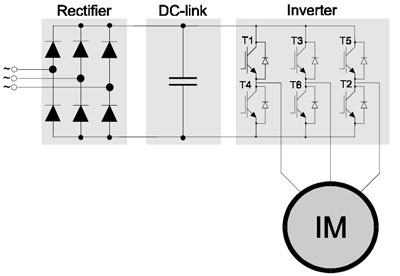
A typical voltage source inverter frequency converter is designed of three power sections: AC/DC converter (rectifier), DC-link, and DC/AC inverter.
Control of frequency converters can be done as open-loop or closed-loop control. For higher performance frequency converters the last mentioned may apply field-oriented control.
Semiconductor Technologies
Today's PWM frequency converters employ a several types of semiconductor devices in the inverter. These are:
The IGBT transistor is a combination of the BJT and the MOSFETs. It has the MOSFET's desired features on the input and the BJT's best features on the output. The IGBT are well suited for VSI frequency converters. The main advantages are the power range, the good conductive features, the high switching frequency and the simple control.
Some typical parameters of the most used power switching devices offers the table below
Induction motor running above rated speed should be confirmed with the manufacturer. PWM frequency converter can output frequencies up to 400 Hz. However, the induction motor's mechanical design, in terms of bearings and balancing, limits the maximum frequency on which it can be operated in good condition. The power supplied to the induction motor by a PWM frequency converter has some disadvantages too (increased heating, high peak voltages, and increased operation noise). Most industrial applications in the power range from less than 1 kilowatt up to some hundred kilowatts make use of Voltage Source Inverter (VSI) type converters.
A typical voltage source inverter frequency converter is designed of three power sections: AC/DC converter (rectifier), DC-link, and DC/AC inverter.

- The rectifier takes the three phase, fixed voltage, fixed frequency power source from the AC power lines and converts it to DC voltage. It obviously uses six power diodes in a three phase full-wave bridge configuration.
- The DC-link takes the DC voltage from the rectifier and filters it to provide a smoother fixed DC voltage to the inverter. This is commonly called the DC bus voltage. It uses filter capacitors in the configuration shown.
- The DC/AC inverter takes the filtered DC voltage and creates three phase variable voltage and frequency power for the induction motor. It uses six power switches in a three-phase bridge configuration. Controlling the on/off duty cycle of each switch along with the sequencing and timing among the switches creates the variable frequency, voltage and phase rotation.
Control of frequency converters can be done as open-loop or closed-loop control. For higher performance frequency converters the last mentioned may apply field-oriented control.
Semiconductor Technologies
Today's PWM frequency converters employ a several types of semiconductor devices in the inverter. These are:
- Thyristors plus External Commutation Network
- Bipolar Junction Transistors (BJTs)
- MOS Field Effect Transistors (MOSFETs)
- Insulated Gate Bipolar Transistors (IGBTs)
- Gate Turn-off Thyristors (GTOs)
- MOS Controlled Thyristors (MCTs)
The IGBT transistor is a combination of the BJT and the MOSFETs. It has the MOSFET's desired features on the input and the BJT's best features on the output. The IGBT are well suited for VSI frequency converters. The main advantages are the power range, the good conductive features, the high switching frequency and the simple control.
Some typical parameters of the most used power switching devices offers the table below
|
Type |
Voltage (UCE) |
Current |
Power |
Switching frequency |
|
Thyristor |
4 kV |
3 kA |
1-100 MW |
500 Hz |
|
GTO |
3.5 kV |
2.5 kA |
1-10 MW |
500 Hz |
|
BJT |
1.2 kV |
600 A |
1-500 kW |
2 kHz |
|
MOSFET |
500 V |
30 A |
0.1 kW |
1 MHz |
|
IGBT |
1.4 kV |
300 A |
1-100 kW |
10 kHz |
Post a Comment:
You may also like:

