Category

Transformer Power Supply
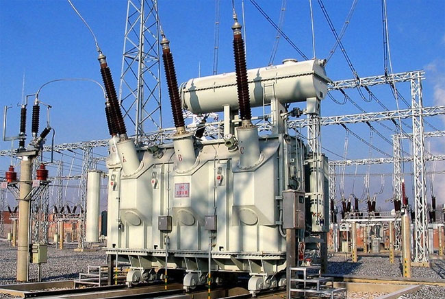
As you connect the secondary of the 700kVA one phase to one primary phase of the 500kVA transformer. Ground the neutral of the 700kVA solidly and ignore it from now on. The primary of the 500kVA has no neutral connection. From the voltages you list I believe that the secondary of the 500kVA is also Wye. So ground it and take the neutral to any of the single phase loads. The breaker on the secondary should be sized to protect the conductors for it to the 500kVA transformer. The 500kVA should be protected by a breaker rated 115% of the rated current of the transformer. I do not have my calculator handy, but I believe that 500kVA at 230V is 1,260A. 115% of that is approx. 1500A You will need to look at the size of the conductors connecting these two to determine the breaker size at the secondary of the 700kVA transformer.

All large power supply systems (sized to power cities) need to have frequency and voltage relays to drop load when the system begins its oscillation (when generation and load are out of balance). This is done to attempt to match load and generation. I live in the Western US have seen large scale load drops (large portions of cities, affecting millions of customers) due to large transmission line outages that caused a mismatch in generation vs load, causing voltage and frequency oscillation, which in turn tripped off loads (over and under frequency and voltage relays). This large scale drop in loads (at different frequencies and voltages, done in stages) finally matched generation to loads and stabilized the system. Depending on the size of your system, stages of frequency and voltage relays connected to most of the distribution circuits can help prevent a total collapse of your power supply system.
Your design looks like this: one step down transformer 13.8kV/231VY; customer want 400VY; you have another step down 400V/230V Aut-Trx. Now the power supply 13.8kV with the load of 400V and 230V. How about this: build a bus bar at the secondary of the 13.8kV/231V and treat others as loads, such as for the 230V load, pick up the power from this bus bar, and use the Aut-Trx as step up transformer to feed the 400V load only. You need to calculate and distribute the load current through the aut-trx and main transformer and set up the proper protection carefully and make sure there is no transformer over load. If you want to add one 230V/400V transformer, you can still distribute some loads through the 13.8kV/231V transformer by a bus bar at the secondary transformer (with 200kVA room). For the star point of aut-trx, primary side grounded and secondary side goes to the load (4w).
Dear Sir
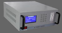
We are looking for a static frequency converter for our client Malaysia Transformer manufacturer which they intend to test cast resin transformer with 2500KVA 33KV as per IEC standard. pls recommend suitable unit to us.
We are looking for a static frequency converter for our client Malaysia Transformer manufacturer which they intend to test cast resin transformer with 2500KVA 33KV as per IEC standard. pls recommend suitable unit to us.
Post a Comment:
You may also like:


We are looking for a static frequency converter for our client Malaysia Transformer manufacturer which they intend to test cast resin transformer with 2500KVA 33KV as per IEC standard.pls recommend suitable unit to us.